DxDrawMaterialPrimitive3D: Difference between revisions
m (→Remarks) |
|||
| Line 42: | Line 42: | ||
[[File:D3d9_screen_space_transformation.png|frameless|center|Direct3D 9 screen-space transformation]] | [[File:D3d9_screen_space_transformation.png|frameless|center|Direct3D 9 screen-space transformation]] | ||
To transform the coordinates you first have to flip the Y coordinate using negation and then apply the Direct3D 9 screen-space rasterization cross-hair by using the screen dimensions (sw, sh). | To transform the coordinates you first have to flip the Y coordinate using negation and then apply the Direct3D 9 screen-space rasterization cross-hair by using the screen dimensions (sw, sh). Since linear shapes are being preserved across linear translations, you can simplify each vertex-based figure into it's set of vertices for the purpose shown above. | ||
==Example== | ==Example== | ||
Revision as of 12:45, 11 January 2022
This function draws a 3D primitive shape with material applied to it in the 3D world - rendered for one frame. This should be used in conjunction with onClientRender in order to display continuously. If image file is used, it should ideally have dimensions that are a power of two, to prevent possible blurring. Power of two: 2px, 4px, 8px, 16px, 32px, 64px, 128px, 256px, 512px, 1024px...
Syntax
bool dxDrawMaterialPrimitive3D ( primitiveType pType, mixed material, bool postGUI, table vertice1 [, table vertice2, ...] )
Required Arguments
- pType: Type of primitive to be drawn.
- image: Either a material element or a filepath of the image which is going to be drawn. (.dds images are also supported). Image files should ideally have dimensions that are a power of two, to prevent possible blurring. Use a texture created with dxCreateTexture to speed up drawing.
- postGUI: A bool representing whether the line should be drawn on top of or behind any ingame GUI (rendered by CEGUI).
- vertices: Tables representing each primitive vertice, required amount of them is determined by primitive type.
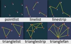
Allowed types
More info on primitives may be found on this MSDN site
- pointlist: Renders the vertices as a collection of isolated points.
- linelist: Renders the vertices as a list of isolated straight line segments.
- linestrip: Renders the vertices as a single polyline.
- trianglelist: Renders the specified vertices as a sequence of isolated triangles. Each group of three vertices defines a separate triangle.
- trianglestrip: Renders the vertices as a triangle strip.
- trianglefan: Renders the vertices as a triangle fan.
Vertices format
- posX: An float representing the X position of the vertice in the GTA world.
- posY: An float representing the Y position of the vertice in the GTA world.
- posZ: An float representing the Z position of the vertice in the GTA world.
- color (optional): An integer of the hex color, produced using tocolor or 0xAARRGGBB (AA = alpha, RR = red, GG = green, BB = blue). If it's not specified, white color is used.
- u: An float representing the relative X coordinate of the top left corner of the material which should be drawn from image
- v: An float representing the relative Y coordinate of the top left corner of the material which should be drawn from image
Returns
Returns a true if the operation was successful, false otherwise.
Remarks
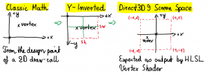
When a 3D draw call is issued by any such material MTA function then the principle to push it directly to the 3D adapter does apply. To achieve this there is no software-side 3D clipping mathematics being performed. This way the vertex data is always being pushed to the vertex shader, leaving the entire freedom to the developer on how to interpret this vertex data in the shader. For example, even though this function does imply an use in 3D world space, the vertex coordinates could be translated directly into Direct3D 9 screen space instead, effectively discarding any multiplication with the camera projection matrix. The mathematical model for translation into valid Direct3D 9 screen-space coordinates is described here. Let's assume that you are drawing the rectangle on a classic sheet of paper with a mathematical 2D X,Y coordinate system.
To transform the coordinates you first have to flip the Y coordinate using negation and then apply the Direct3D 9 screen-space rasterization cross-hair by using the screen dimensions (sw, sh). Since linear shapes are being preserved across linear translations, you can simplify each vertex-based figure into it's set of vertices for the purpose shown above.
Example
| Script Example Missing Function DxDrawMaterialPrimitive3D needs a script example, help out by writing one. | |
Before submitting check out Editing Guidelines Script Examples. |
-- TODO
This function can be used to draw billboards in the game world. You have to understand the mathematical models about the human vision to calculate the proper vertices.
Requirements
This template will be deleted.
See Also
- dxConvertPixels
- dxCreateFont
- dxCreateRenderTarget
- dxCreateScreenSource
- dxCreateShader
- dxCreateTexture
- dxDrawCircle
- dxDrawImage
- dxDrawImageSection
- dxDrawLine
- dxDrawLine3D
- dxDrawMaterialLine3D
- dxDrawMaterialPrimitive
- dxDrawMaterialPrimitive3D
- dxDrawMaterialSectionLine3D
- dxDrawPrimitive
- dxDrawPrimitive3D
- dxDrawRectangle
- dxDrawText
- dxDrawWiredSphere
- dxGetBlendMode
- dxGetFontHeight
- dxGetMaterialSize
- dxGetPixelColor
- dxGetPixelsSize
- dxGetPixelsFormat
- dxGetStatus
- dxGetTextSize
- dxGetTextWidth
- dxGetTexturePixels
- dxIsAspectRatioAdjustmentEnabled
- dxSetAspectRatioAdjustmentEnabled
- dxSetBlendMode
- dxSetPixelColor
- dxSetRenderTarget
- dxSetShaderValue
- dxSetShaderTessellation
- dxSetShaderTransform
- dxSetTestMode
- dxSetTextureEdge
- dxSetTexturePixels
- dxUpdateScreenSource

